When Heat Becomes the Invisible Enemy of the PCB
🖋️ Par Stefano Morlacchi
CAE Application Engineer at Var Industries S.A.S.
🖋️ Par Stefano Morlacchi
CAE Application Engineer at Var Industries S.A.S.
with speed and precision
Even with a perfectly routed PCB and a flawless copper layout, a discreet phenomenon can destabilize everything: thermal rise.
Engineers know it well: a deviation of just a few degrees can compromise the reliability of an entire product. Yet accurately modelling this reality remains a major challenge. Traditional tools only "see" averaged materials. Full 3D modelling, on the other hand, demands excessive computation time.
So how can you capture the true thermal behaviour of a PCB without sacrificing precision or design cycles?
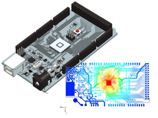
This is where SMART PCB, Siemens technology integrated into Simcenter FLOEFD and Simcenter Flotherm, comes into play.
Instead of simplifying the board, SMART PCB does the opposite: it uses the native electronic design data with full-fidelity detail.
Supported formats include ODB++, IPC-2581B, CCE, and more.
This means:
- Copper planes remain copper planes
- Trace widths stay exactly as routed
- Thermal vias keep their exact distribution
- The stack-up is imported exactly as designed
No reconstruction. No guesswork. No approximations.
The thermal model reflects the actual PCB, not a theoretical version of it.
SMART PCB converts the routed PCB layout into a network of thermal resistances.
Copper regions receive low thermal resistance; dielectric regions receive higher resistance. Just like in real life, heat flows through the exact paths it would take on the physical board.
Two resolution modes are available:
- Fine mode: maximum fidelity, ideal for critical traces
- Averaged mode: faster computation, perfect for early-stage iterations
The equation is simple: less computation, more accuracy.
Because a PCB is never just thermal, SMART PCB also enables electro-thermal co-simulation with HyperLynx™ PI (DC Drop).
During each simulation cycle:
- The thermal model sends updated temperature results
- HyperLynx PI recalculates copper electrical resistance based on temperature
- A new Joule heating power map is sent back to the thermal solver
You gain a fully realistic view of:
- Current density
- Voltage drops
- Critical hot zones and high-stress areas that may cause failures
This is the ideal closed-loop workflow to understand why a PCB heats up — and how to prevent it.
SMART PCB also enables a full thermo-mechanical workflow in Simcenter FLOEFD:
Thermal simulation temperatures become direct input for a linear structural analysis.
➡️ The tool computes stresses, warpage, deformation…
➡️ Without ever requiring explicit CAD geometry or simplification of vias and traces.
A major time saver for reliability investigations such as:
- PCB warpage
- Mechanical stress failures
- Thermal fatigue during operation or manufacturing
SMART PCB transforms the way engineers predict, understand, and master the thermal behaviour of a PCB.
In a world where every watt counts and every degree can decide the fate of a product, such precision is no longer optional — it’s a strategic advantage.
Contactez-nous pour découvrir comment nous pouvons vous accompagner concrètement.