Solid Edge helps you overcome electromechanical design challenges with a dedicated solution for electrical design.
Solid Edge is no longer just a parametric three-dimensional CAD but an entire portfolio of solutions that enable true collaboration and co-design between electrical and mechanical domains, without ever leaving the single, shared environment. The benefits of this are reduced development time and instantaneous verification of the impact of changes, ensuring that working products are obtained and reducing the cost of physical prototyping.
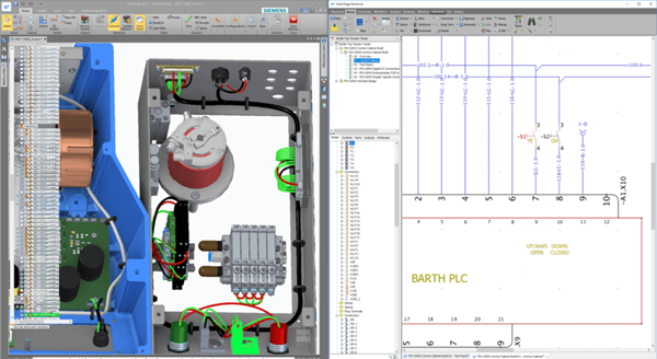
Solid Edge Wiring Design
Solid Edge Wiring Design enables quick and intuitive design of electrical circuits using industry-proven tools that simulate and verify electrical behavior during design creation. The graphical design environment creates wiring diagrams through an intuitive user interface and built-in libraries of electrical symbols, components, and simulation models.
The Wiring Design tool in Solid Edge automates the generation of standards-based diagrams and cross-references for multi-sheet diagrams and automatically generates reports for cables, connectors, and devices used in a project.
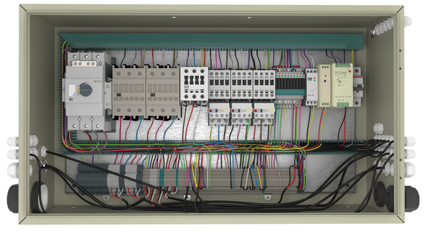
Why choose Solid Edge Wiring Design?
- Simple collaboration between ECAD and MCAD.
- Virtual prototyping of circuits.
- Optimization of design.
- Creation of cabinet layouts.
Want to learn more about electrical design with Solid Edge Electrical?
Download the product sheet:
Solid Edge Harness Design
Solid Edge Harness Design is a graphical design application for creating harness and formboard designs, suitable for both in-house production and build-to-print operations.
It uses a controlled and optimized correct-by-design process to ensure digital continuity across domains, enabling engineers to bring products to market faster and with greater confidence.
Why choose Solid Edge Harness Design?
-
Integrated libraries of symbols and components
-
Flexible options for cable design
-
Advanced reporting tools for technical documentation
-
Creation of formboard layouts
-
Design automation and real collaboration between ECAD and MCAD
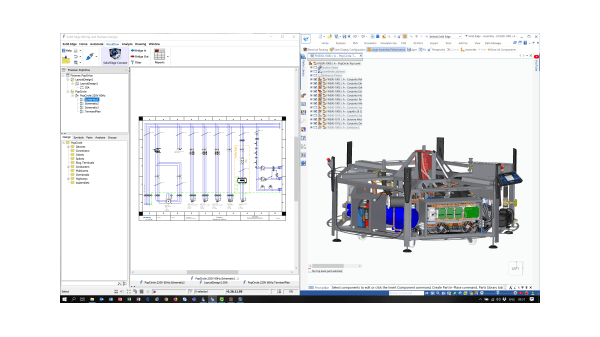
Solid Edge Electrical Routing
Solid Edge Electrical Routing is a dedicated, process-driven environment for the efficient creation, routing, and organization of wires, cables, and bundles in mechanical assemblies, providing the ability to easily transfer wiring harness topology data between ECAD/MCAD systems, reducing design time and accelerating delivery to production.
Why choose Solid Edge Electrical Routing?
- Simple creation of structured workflows.
- Detection of design violations in real time.
- Comprehensive digital mockups.
- Total collaboration with all major ECADs in the market.
Solid Edge PCB Design
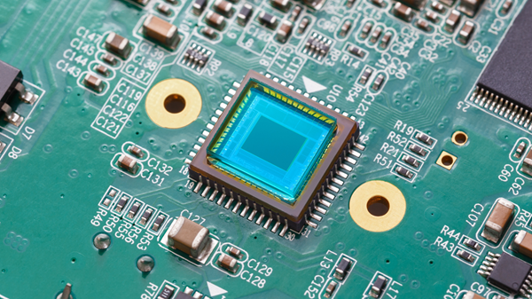
Solid Edge PCB Design enables synchronization of the electromechanical aspects of circuit board designs with tools for PCB layout and schematic capture, which avoid the costs associated with reformulating mechanical and circuit board designs.
This tool allows ECAD-MCAD design teams to collaborate in real time, resolving critical aspects of electromechanical design early in the design cycle.
Why choose Solid Edge PCB Design?
- Speed up product development activities.
- View design problems within a 3D PCD environment.
- Presence of part libraries and repositories.
- Accelerates acquisition and layout activities.
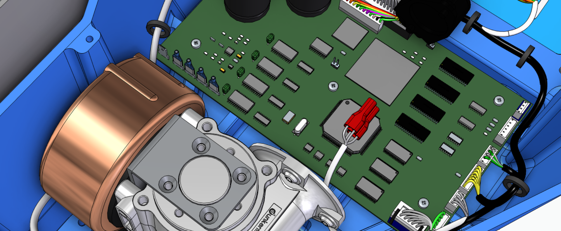
Solid Edge PCB Collaboration
Solid Edge PCB Collaboration removes barriers between ECAD-MCAD environments by efficiently communicating design intent between domains, allowing engineers to remain in their individual environments
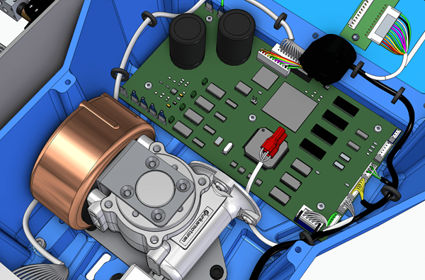
The software provides intuitive 3D visualization of both the printed circuit board and its casing, allowing easy creation and export of the design intent of the PCB.
A photorealistic view of the PCB components helps in the accurate electromechanical design of the product.
Request more information or your custom quote