Designing the dissipation of heat produced by joule effect, 2 practical examples

The Joule effect is one of the main phenomena that occurs in electronic equipment when electrical energy is converted into thermal energy. In summary, the Joule effect consists of the generation of heat that arises when an electric current flows through a circuit element between two points characterized by a certain potential difference.
The Joule effect, in some cases, is intentional, as in fuses, hair dryers, or electric ovens, but in most cases, it is an unavoidable consequence of the passage of current, which produces unwanted and potentially harmful heat. For those involved in thermal simulation in the design of electronic devices, it represents a problem that must be thoroughly understood within a 3D design environment.
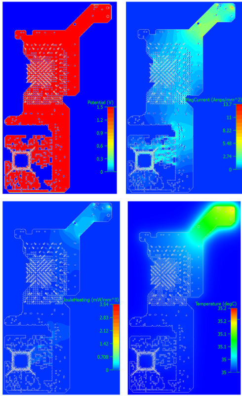
The Joule effect can be effectively analyzed and managed using a tool such as Simcenter FloTHERM XT, the thermal simulation software integrated into PADS Professional, the PCB Design suite developed by Mentor and Siemens for small and medium-sized electronic design companies. In the latest versions of FloTHERM XT, electrical boundary conditions are applied to the periphery of a 3D solid representation of the conductor. The subsequent 3D electro-thermal simulation process calculates the current, potential, and voltage and uses the Joule heating power as a cell-by-cell source for the temperature distribution.
Typical application areas for simulating the heat generated by the Joule effect include busbars, power substrates, and BGA ground planes, as well as leadframes and fuses. These are cases in which heat due to electrical resistance plays a dominant role in total power dissipation.
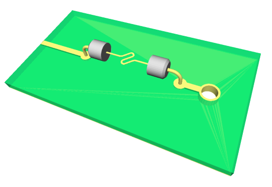
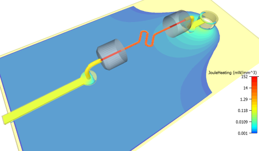
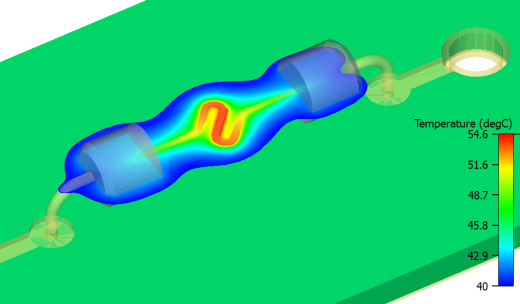
The role played by the fuse involves a coupling between the electrical and thermal worlds. An increase in temperature will result in an increase in electrical resistivity, which in turn will increase current density, which will increase Joule heating power, which will increase temperature, and so on. If the heat is removed quickly enough, equilibrium is achieved and conditions stabilize at a constant temperature rise. If the coupling is too strong, especially under high current conditions, the temperature will soar, as long as the fuse does not overheat. FloTHERM XT can handle this coupling through its material property of temperature-dependent electrical resistivity.